Installation
Always turn your eurorack case off before plugging or unplugging a module.
Do not touch any electrical terminals when attaching any Eurorack bus board cable.
Ritual Electronics Miasma requires:
- 35 mA +12V
- 30 mA -12V
- 0 mA 5V
You will need 10HP of free space in your Eurorack case to install Miasma.
Connect the included ribbon cable to the module. Connect the other end of the cable to the bus board connector of your case.

Overview
Miasma is a voltage controlled distortion with a feedback loop you can push to self oscillation for insane results and interchangeable rectification diodes, giving you an unlimited amount of sound possibilities within one module.
Miasma’s feedback path feeds the distorted signal back in the input with no phase inversion, causing the module to self oscillate, even with no input. The feedback path can be opened to send
it through different effects making Miasma perfect for complex feedback patches.
A blend knob allows Miasma to be use in a precise way, for more complex sound design.
The module’s clipping diodes are mounted on a header making it easy to change them and craft the sound you want.
There module ships with six different diodes, from germanium
to LEDs and you can experiment adding your own. The output level may vary depending on which diodes you use, this can be adjusted with the level trimmer on the front panel.
Controls
- Gain control up to +20dB
- Feedback VCA
- Blend control between dry and wet signal
- Attenuverters on Gain and Feedback CV
- Level trimmer to adjust the output volume
Technical characteristics
- OTA based VCAs for gain and feedback control
- Feedback output jack is normalized to the feedback input jack
- One rectification diode per waveform polarity, for symmetrical or asymmetrical distortion
- Diodes can be swapped in and out without the need of tools
Dimensions
- 37 mm deep
- 10HP large
- 3U
Controls
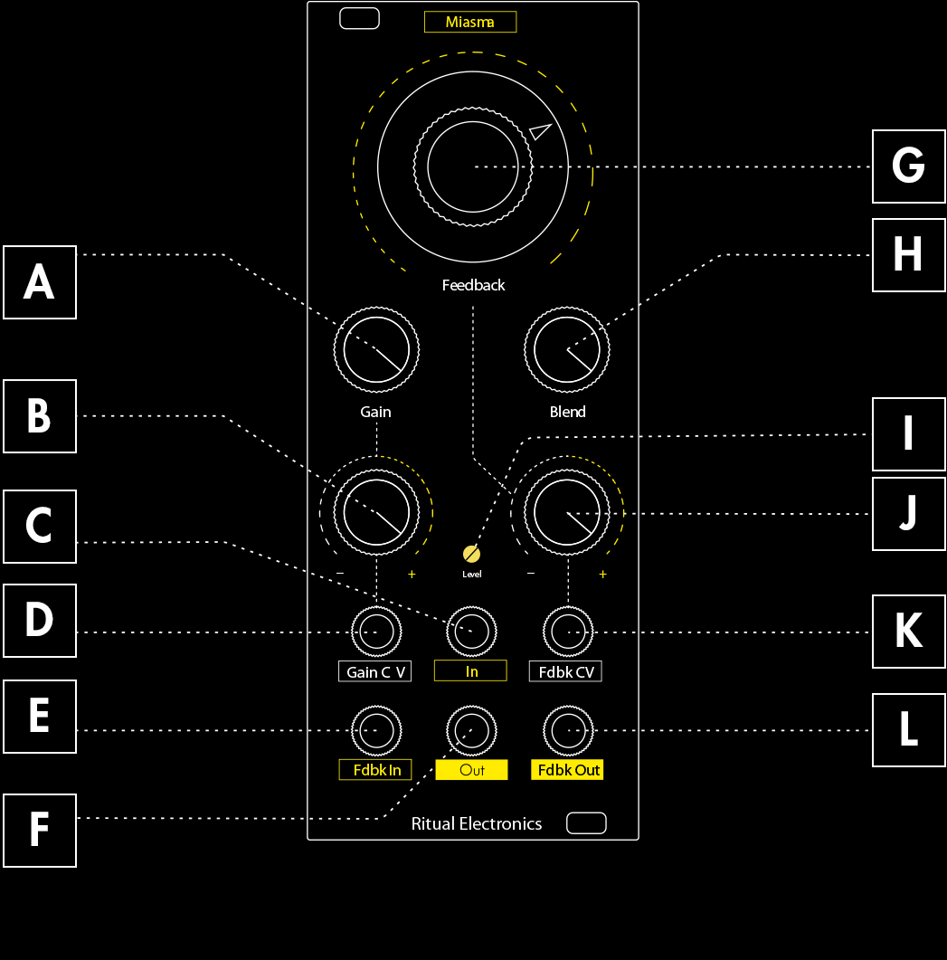
A – Gain knob
Set the initial amount of gain applied to the input signal.
B – Gain attenuverter
Set the amount of CV applied to the gain parameter. CW adds up to the gain knob position, CCW substracts.
C – Audio input
100k impedance – the input signal voltage greatly influences the effect.
D – Gain CV input
CV input (-5/+5V).
E – Feedback loop input
Feedback input is normalized to the feedback output jack. A jack breaks the loop.
F – Audio output
1k impedance.
G – Feedback knob
Set the initial amount of distorted signal feeding back into the distortion circuit.
H – Blend knob
Fully counter clockwise is the dry signal Fully clockwise is 100% wet
J – Level trimmer
Set the output volume – it doesn’t affect the overall distortion effect.
I – Feedback attenuverter
Set the amount of CV applied to the feedback parameter.
K – Feedback CV input
CV input (-5/+5V).
L – Feedback loop output
Outputs the feedback signal – nothing is present if there is no feedback.
Block Diagram
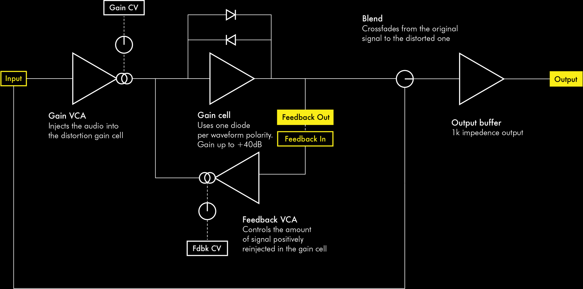
Diodes
Miasma uses two diodes to rectify the signal. These diodes define the colour of the sound. By making these diodes interchangeable you can achieve a great palette of sounds.
The diodes create a different shape of distortion. There is one diode per waveform polarity, to achieve asymetrical distortion.
The diodes influence both the distortion sound and the feedback texture and pitch. See the waveforms on the adjacents illustrations.
Different diodes have different current and voltage consumption, this can yield to volume increase or decrease from a configuration to an other.
Miasma is shipped with 6 different type of diodes:
- 1N4148
- 1N914
- BAT42
- 1N60
- Blue LED
- Red LED
You can of course try your own!
Follow the instructions and only put diodes in the header. Anything else put in the diode header will void your warranty.
Diodes Mount
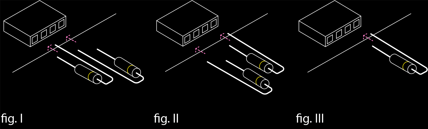
Always disconnect Miasma from the power supply before changing the diodes!
The female header on which the diodes are mounted is located on the back PCB board of Miasma. You can access the header without disassembling the module. Though the use of twizzers is recommended if you don’t take the back board appart from the top one.
fig. I & fig. II
These are both valid ways to mount the diodes if you want to rectify both sides of the waveform
fig. III
By using only one diode, you’ll create asymetrical distortion and rectify only one side of the waveform (it is recommended to do so with the germanium diode which sucks a lot of sound and prevents feedback when combined with another type of diode)
Observations
A distortion is a waveshaping effect, it is best used with simple frequencies with little frequency content. A sine wave, a triangle wave or a filtered sound will be more affected by Miasma.
The input level affects the overall sound of the distortion. Try running your signal in an amplifier or attenuator to increase Miasma’s sound possibilities.
When the gain increases the feedback decreases. When the gain is pushed to the max you may not hear any feedback, the two parameters are related.
Different diodes lead to different output levels. This can be corrected using the “Level” trimmer on the front panel.
Patch Ideas
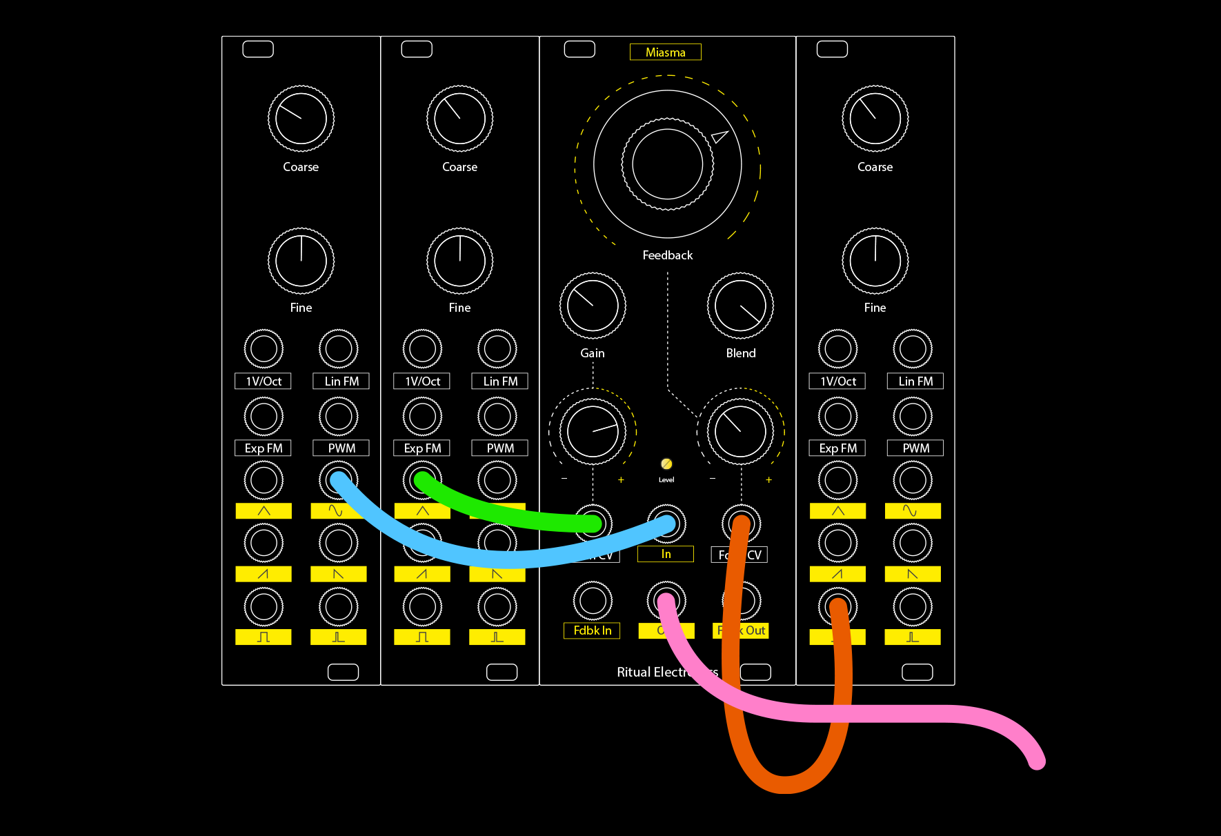
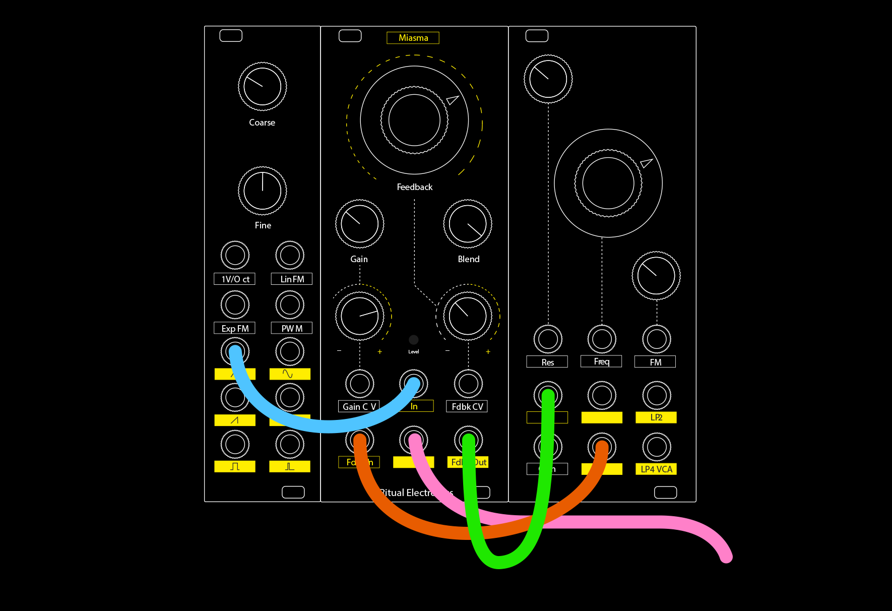
Patch #1 – Audio Rate Modulations
The modulation buses in Miasma respond extremely well to audio rate modulations. Try to modulate both the gain and the feedback at audio rate to achieve great effects.
Adjacent frequencies will produce beating effect for really doomy effects.
Tuned frequencies are kind off mixed together which can result in chord-like effects.
Patch notes
Oscillator 1, sine wave out ———— Miasma In
Oscillator 2, triangle wave out ———— Gain CV
Oscillator 3, square wave out ———— Feedback CV
Adjust the attenuverters for a deeper effect.
The output can be patched to a filter or other processing modules for further sound design.
Patch #2 – Tuned Feedback
When a sound processing module is connected between the Feedback Out and the Feedback In it is pushed into feedback. It causes a filter to self oscillate in a special way. This way you can tune Miasma’s feedback. It is particularely useful when used with a drum sequence or a tuned synth line.
Patch notes
Oscillator, triangle wave out ———— Miasma, audio in
Miasma, feedback out ———— Filter, audio input
Filter, output ———— Miasma, feedback in
Tune the filter according to your oscillator.
Try to use the same 1V/Oct signal in the oscillator and in the filter FM, this will harmonize both lines
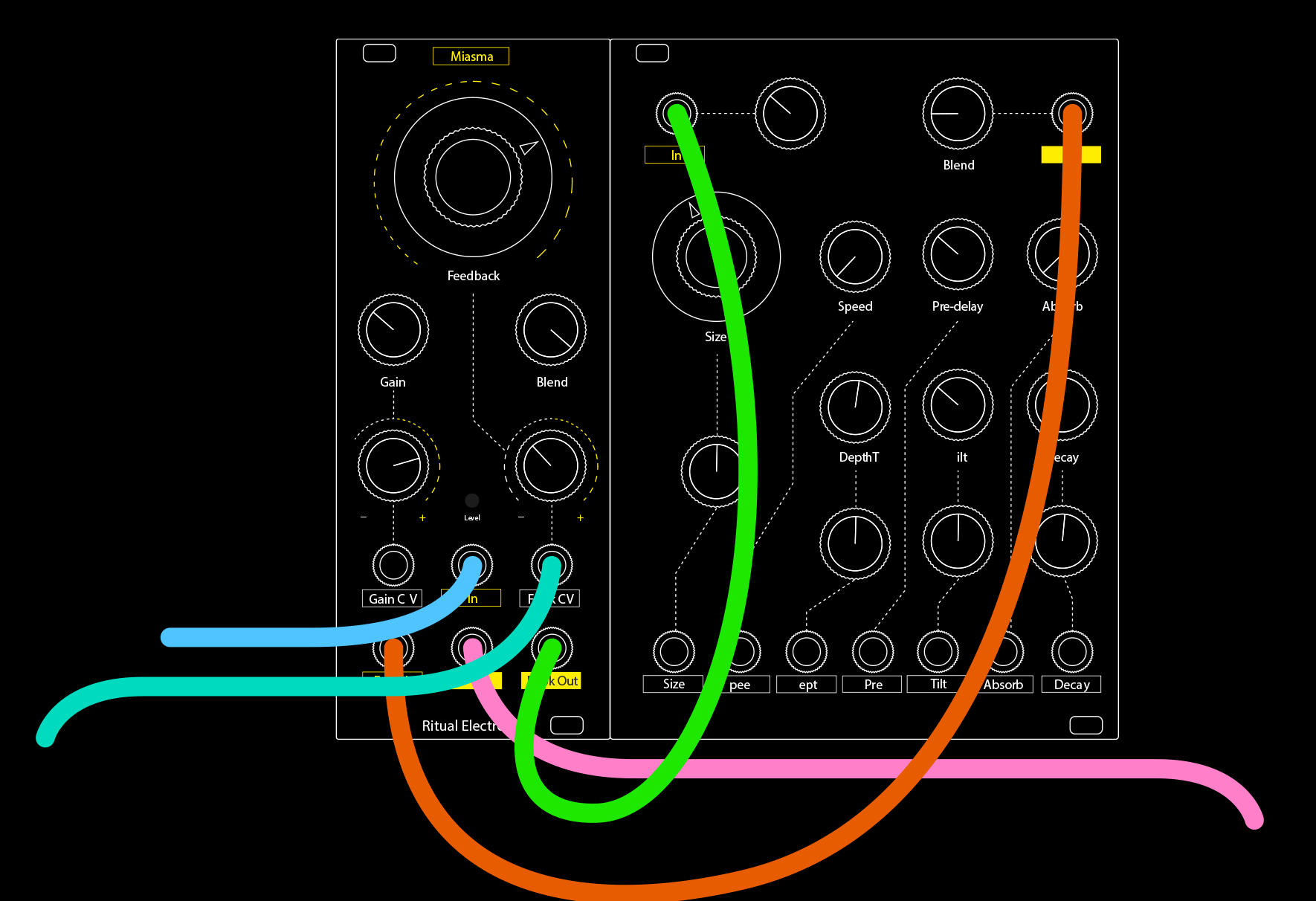
Patch #3 – Doom Reverb
Inserting a reverb in the feedback path will result in pretty wild feedback sounds. With the right settings it can sound like guitar amp feedbacks.
Depending on your reverb, further processing may have to be patched to achieve this sound.
Patch notes
Synth / Drum line ———— Miasma, audio in
Miasma, feedback out ———— Reverb, audio input
Reverb, output ———— Miasma, feedback in
Envelope / LFO / random ————- Miasma, feedback CV
Changing the reverb parameters will affect the sound.
Play with the dry/wet parameter of your reverb.
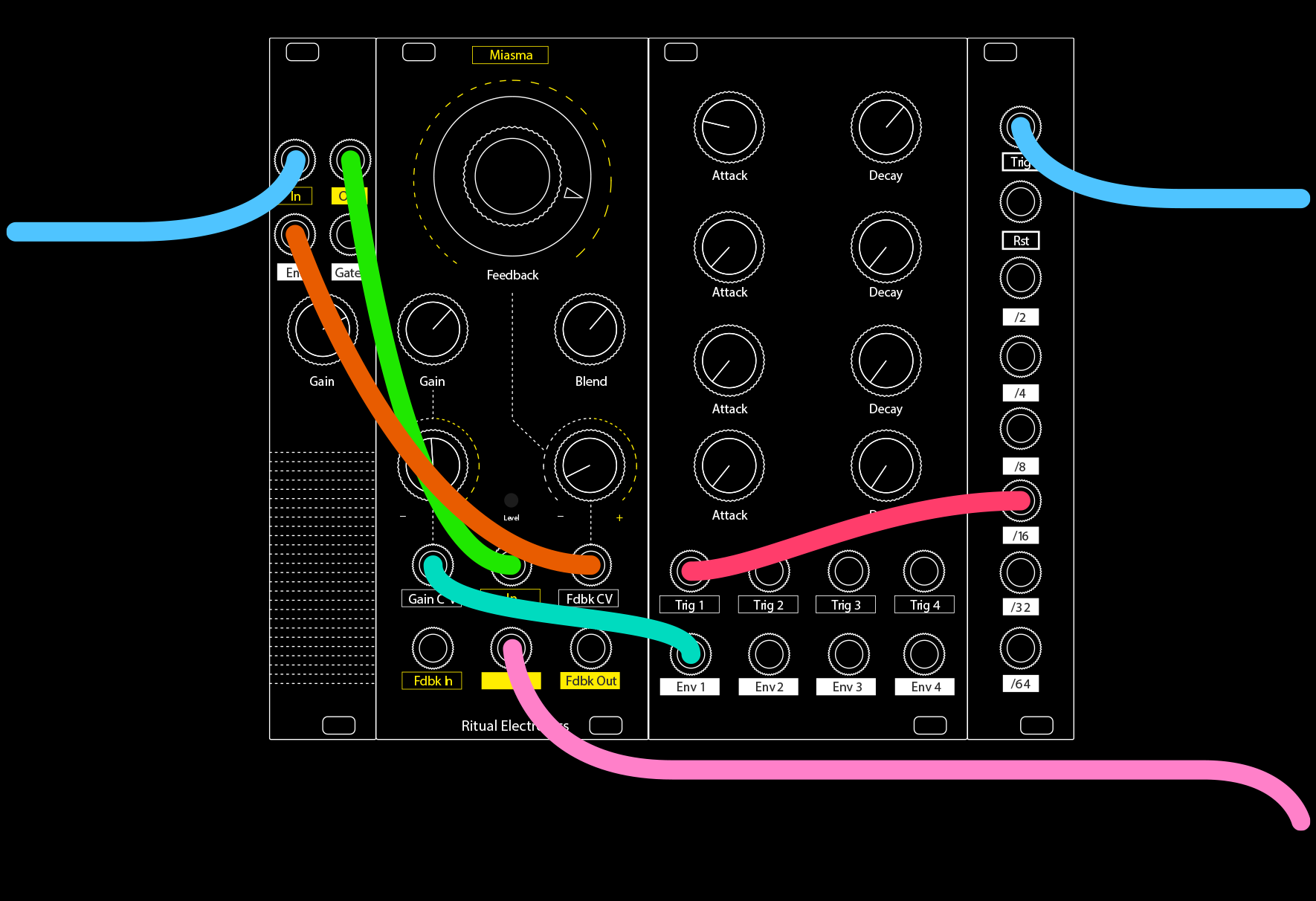
Patch #4 – Drum Smasher
Miasma is great at handling highly dynamic signals like drums. Signals with lots of transient tend to cut through the feedback.
Try running a kick drum with feedback open, it will make the feedback “pump”.
When processing a drum bus, or more complex signals, try using a attenuator + pre-amp to adjust the input gain for more sound design options.
Patch notes
Synth / Drum line ———— Amp + Envelope follower, audio input
Amp + Envelope follower, audio output ———— Miasma, audio input
Amp + Envelope follower, envelope output ———— Miasma, feedback CV
Synth / Drum line, clock ———— Clock divider, clock in
Clock divider, divided out ———— Envelope generator, trig / gate in
Envelope generator, envelope output ————- Miasma, gain CV
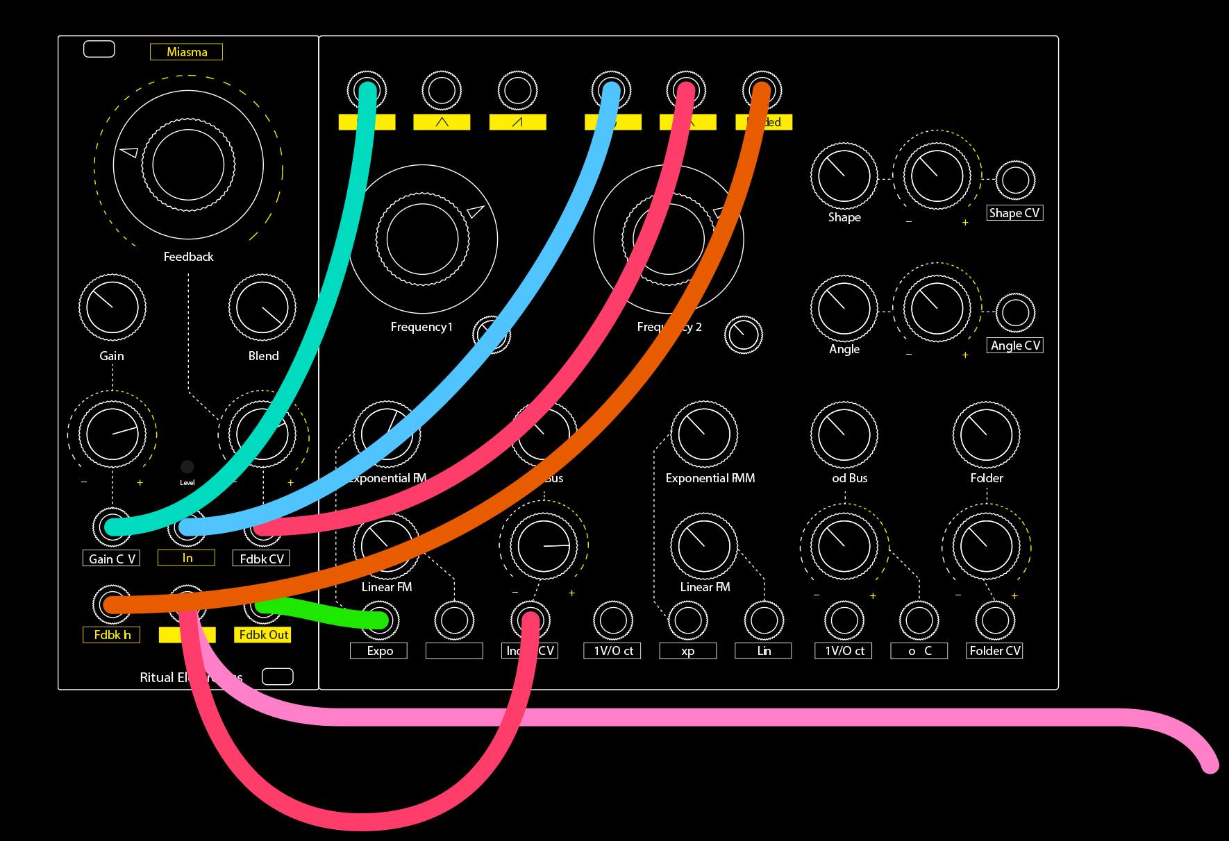
Patch #5 – Harsh Noise Machine
Patching Miasma with a complex oscillator like some sort of feedback harsh noise machine results in earthy distorted sounds.
Just tweak Miasma’s attenuverters and your oscillator FM setting like a mad man for crazy synth noises.
Patch notes
Oscillator 1, waveform 1 ———— Miasma, gain CV
Oscillator 2, waveform 1 ———— Miasma, audio input
Oscillator 2, waveform 2 ———— Miasma, feedback CV
Oscillator 2, final waveform ————- Miasma, feedback in
Miasma, feedback out ————- Oscillator 1, exponential FM
Warranty
Thank you for purchasing Ritual Electronics Miasma.
Your module has been handbuilt with care in Paris, France.
You can find your module on Modulargrid:
https://www.modulargrid.net/e/ritual-electronics-miasma
For any remarks and informations, contact us at:
contact@ritualelectronics.com
For video demos and patch ideas check:
https://www.instagram.com/ritualelectronics/ https://www.youtube.com/c/ritualelectronics
Limited Warranty
Ritual Electronics warrants this product to be free of defects in materials
or construction for a period of one year from the date of purchase.
Malfunction resulting from wrong power supply voltages, backwards
or reversed eurorack bus board cable connection, abuse of the product
or any other causes determined by Ritual Electronics to be the fault of the
user are not covered by this warranty, and normal service rates will apply.
During the warranty period, any defective products will be repaired
or replaced, at the option of Ritual Electronics, on a return-to-Ritual
Electronics basis with the customer paying the transit cost to Ritual
Electronics. The return of your module is on us.
Ritual Electronics implies and accepts no responsibility for harm to person
or apparatus caused through operation of this product.