Installation
Always turn your eurorack case off before plugging or unplugging a module.
Do not touch any electrical terminals when attaching any Eurorack bus board cable.
Ritual Electronics Diviser requires:
- 25 mA +12V
- 3 mA -12V
- 0 mA 5V
You will need 14HP of free space in your Eurorack case to install Diviser. As it’s a 1U module, you will need 1U rack space, in Intellijel format. Please refer to either manufacturer website for complete specifications on their respective format.
As the 1U series does not have a shrouded header, all the modules will be follow the RED STRIPE DOWN norm. Just align the red stripe on your power cable to the line on the module with RED written next to it. Connect the other end of the cable to the bus board connector of your case.
Overview
Diviser is a 1U clock divider with odd & even outputs.
It can divide a signal by 2, 3, 4, 5, 7, 8, 16 and 32 simultaneously.
Being based on CMOS chips it can run at audio speed (and higher) to create subharmonics and/or rhythms from an oscillator.
The reset input resets all the outputs to a high state.
Comparators are built in both the Clock and Rest inputs with threshold set at 2.5V. It means you can use any type of signals in these inputs.
Technical characteristics
- Clock divider/counter
- Built-in comparators on inputs
- Gate to trigger converter on Reset input
- 10V outputs
Dimensions
- 35 mm deep
- 14HP large
- 1U
Controls
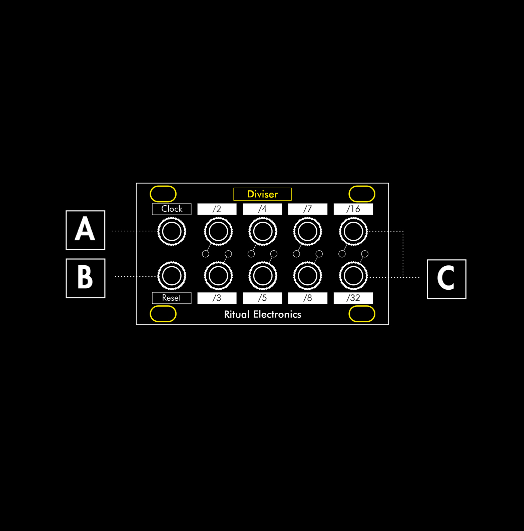
A – Clock Input
Signal to be divided Built in comparator
B – Reset Input
Resets the divider on a High Built in comparator going into a gate to trigger convertor
C – Divided outputs
50% duty cycle 0-10V squares
Divisions

Diviser outputs 8 different clock divisons. Each output has a 50% duty cycle (equal time spent on and off). Here is a visual representation of the different outputs in relation with the clock input.
Counting

We are referring to devices as Diviser as clock dividers. When using a straight clock it is indeed the effect we observe. See diagram above, in Divisions.
If we use a gate sequence in place of the steady clock we can discuss another aspect of Diviser. The chips used in the module are marketed as electronic counters. They do not divide per say, they count the pulses and output accordingly.
Diviser counts the rising edges of incoming pulses. You can then generate slowed down sequences related to your input. Resets can be used to add more pulses to the resulting sequences – see next page.
Reset
Diviser follows what has been known as “musical reset”. Instead of dropping to a Low when the divider receives a reset input, Diviser goes High. It is the expected behavior when you want to reset a divider/ sequencer/… You usually want your module to start the first beat/whatever of the sequence when it receives a trig in Reset.
On top of this there is a gate to trigger in the Reset input. Meaning the signal you put in the Reset can be as long as you want, it will only reset the divider at its rising edge. If you want to pause Diviser we recommend doing it at the Clock input.

This shows how the Reset input behaves. No effect if it is during a high. It will create a High if the effect is triggered during a Low. Here we have a straight clock, an unrelated trigger pattern in the Reset in, and the resulting pattern is taken from the /2 output.

When using an odd division output, you can make use of an even division to reset it back when a bar starts for example. Here you can see a straight beat, a reset signal taken from the /8 output and the resulting pattern at output /3.
Patch Ideas
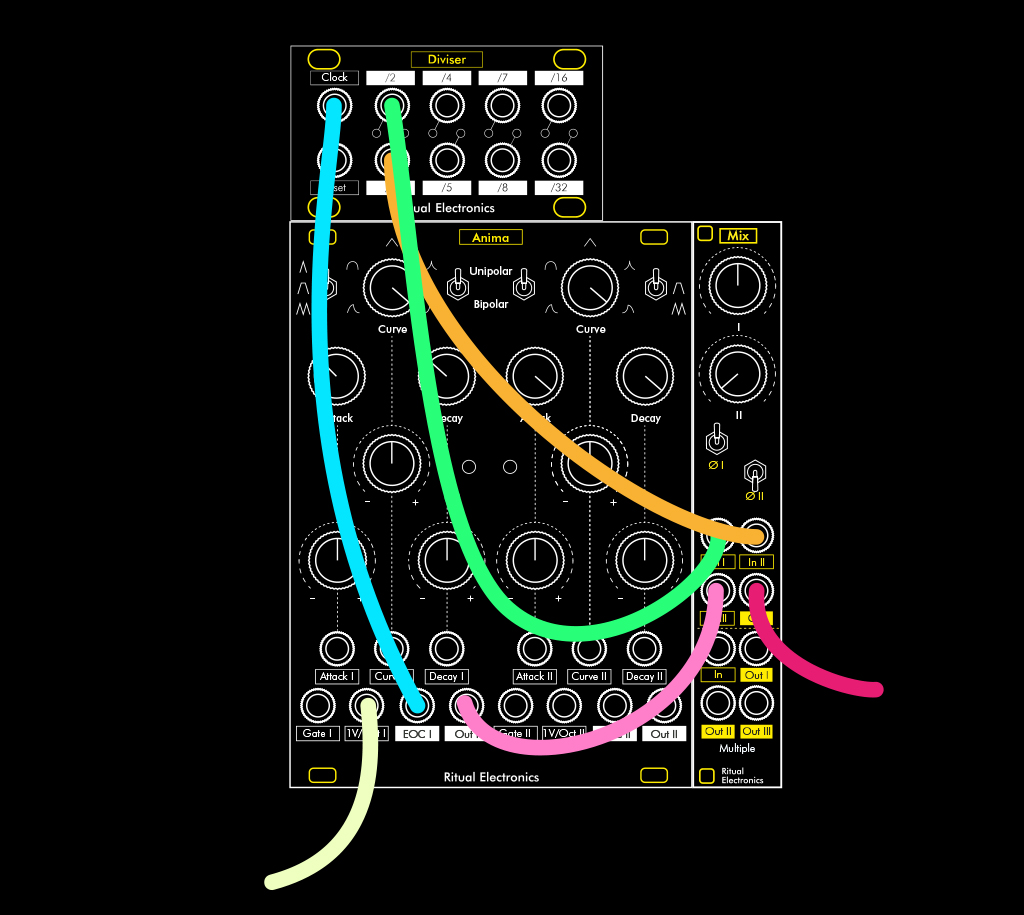
Patch #1 – Harmonic oscillator
Diviser can take high frequency audio at its input and act as a sub oscillator. Mixing the outputs together with the oscillator you can get a really thick sounding oscillator.
Note that Diviser outputs unipolar gates, you may want to offset them by -5V for best results. Or as pictured, inverse the phase of one of the divisions.
The odd divisions will give you second, forth and sixth intervals, octaves down.
You may want to use a faster than usual oscillation.
You can play with the reset input to find beating patterns.
Patch notes
Oscillator, Out ———— Mixer, In
Oscillator, Square Out ———— Diviser, Clock In Diviser, Clock Outs ———— Mixer, Ins
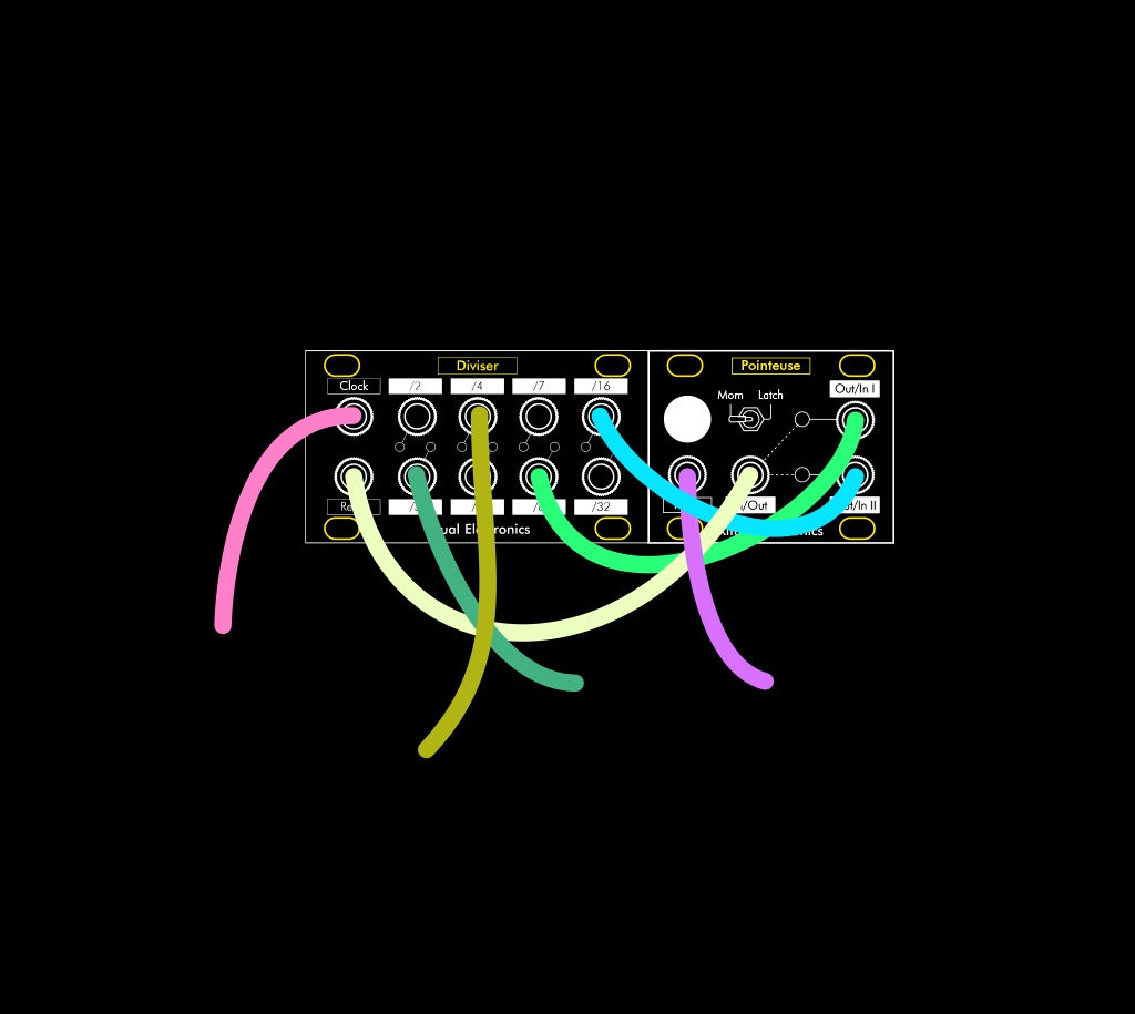
Patch #2 – More complex sequencing
Try switching from different reset divisions with the help of Pointeuse. Clock Diviser from a clock or a sequence of gates. Clock Pointeuse with an unrelated clock for more variations.
Patch notes
Diviser, Clock Outs ———— Pointeuse, Out/In I & II Pointeuse, In/Out ————- Diviser, Reset In
Warranty
Thank you for purchasing Ritual Electronics Diviser.
Your module has been assembled with care in Marseille, France.
You can find your module on Modulargrid:
https://www.modulargrid.net/e/ritual-electronics-diviser-
For any remarks and informations, contact us at:
contact@ritualelectronics.com
For video demos and patch ideas check:
https://www.instagram.com/ritualelectronics/ https://www.youtube.com/c/ritualelectronics
Limited Warranty
Ritual Electronics warrants this product to be free of defects in materials or construction for a period of one year from the date of purchase. Malfunction resulting from wrong power supply voltages, backwards or reversed eurorack bus board cable connection, abuse of the product or any other causes determined by Ritual Electronics to be the fault of the user are not covered by this warranty, and normal service rates will apply.
During the warranty period, any defective products will be repaired or replaced, at the option of Ritual Electronics, on a return-to-Ritual Electronics basis with the customer paying the transit cost to Ritual
Electronics. The return of your module is on us.
Ritual Electronics implies and accepts no responsibility for harm to person or apparatus caused through operation of this product.