Installation
Always turn your eurorack case off before plugging or unplugging a module.
Do not touch any electrical terminals when attaching any Eurorack bus board cable.
Ritual Electronics Aranea requires:
- 70mA on +12V
- 90mA on -12V
- 0mA on +5V
These are the absolute maximum ratings we got with intensive use.
You will need 26HP of free space in your Eurorack case to install Aranea. The module is 38mm deep.
Overview
Aranea is a 5×5 active matrix mixer. It can be used for both audio and CV duties.
There are five inputs (lines) which are mixed to five outputs (columns). This configuration can be used to create five different mixes of the same inputs which can be interesting for CV applications, to create feedback patches using effects, as a mixer for multi channel diffusion or even as a no input mixer.
Each knob is an attenuverter with 1.2x gain. Full attenuation is at noon. To the left, the phase is inverted. To the right, the phase is preserved. Having the choice of in phase or out of phase is very handy for a matrix mixer, whether for CVs or for audio signals. It also helps going from “no sound” to “full on” with only half a pot turn. Handy in Aranea’s dense but playable layout.
Our matrix mixer has a few special outputs. We added mixed outputs for columns A+B and D+E, and diagonal outputs ( “/” and “\” ), which give even more possibilities.
Each output has a soft limiter engaging around 14Vpp. It helps not going too loud and ugly (bad ugly) in feedback patches.

Controls
A – Input I to V
The 5 inputs to the matrix. Each input is spread on the entire line.
B – AC/DC switch
In AC mode it engages DC blocking capacitors on all outputs. In DC mode all signals pass.
C – Output A+B A mix of output A and output B.
D – / Output A mix of the top right to bottom left diagonal.
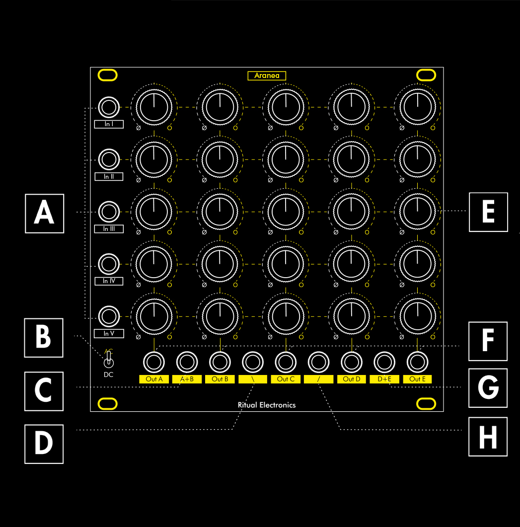
E – 25 Attenuverter knobs The attenuverter is closed at noon. Turning it to the right it opens up in phase, until reaching 1.2X gain. Turning it to the left it opens up out of phase, until reaching -1.2X gain.
F – Outputs A to E The 5 colums outputs. Each is a mix of inputs I to V.
G – Output D+E A mix of output D and output E
H – \ Output A mix of the top left to bottom right diagonal.
About matrices – generalities
A matrix mixer is an electronic device used to route and mix audio and CV signals. It’s particularly useful in the world of modular synthesizers. Let’s find out why.
Of course, you can mix, as the name suggests. It also helps to consider the matrix as a routing hub for different signals.
You can use it to connect multiple audio inputs (signals from your oscillators, filters, etc.) to multiple outputs (going to amplifiers, effects modules, etc.). You can change the way these signals are chained without unplugging cables.
It provides level control (often via knobs) to determine how much of each input signal gets sent to each output. This allows for mixing and combining sounds.
Sometimes, like with our own Aranea, you also have control over the phase of the signal. Not as a phase shifter, but as an attenuverter. In phase, or out of phase.
It is specially useful for effect processing. Patch a sound source to the matrix, then send it to different effects modules, and bring the effected sounds back into the mixer for further manipulation.
Did you know?
The concept of a switch matrix for signal routing first appeared in modular synths like the ARP 2500 (released in 1962) as an alternative to messy patch cables.
These are just a few ideas to get you started.
The beauty of a matrix mixer lies in its flexibility. Experiment with different routings, level adjustments, and combinations with other modules to unlock its full potential and discover unique sonic domains!
.
About matrices – columns

It is just a big mixer after all. Let’s analyze a single column first.
In I to In V are the five inputs of our mixer. Out A is the output of our mixer.
The mixer is of the bipolar kind, meaning it can go from silent to loud in phase or from silent to loud out of phase. In other words, the pots are attenuverters instead of simple attenuators.
This mixer has an AC/DC switch to chose audio or CV mode (more on that later in the manual).
Each of the 5 columns labelled A to E are electronically identical.
This should be pretty straight forward. Next page let’s have a look at a row.
About matrices – rows
A column is one instance of mixer. A row is a router.
We have seen In I goes to Out A along with the other inputs.
Ins also spread horizontally. They are distributed to the 5 columns.
When you combine the horizontal distribution and vertical mixing, you get 5 mixers sharing the same 5 inputs.
Why would you want 5 different mixes of 5 inputs? Multi diffusion of sound through up to 5 speakers can be a valid answer. Auxiliary send to effects can be done this way too. 5 different mixes of 5 CV sources sent around your patch is great to get a lot of complex modulations around.
But it is when patched creatively that the concept becomes the most interesting.

AC/DC modes

A special feature of Aranea is its single AC/DC switch.
Instead of having a switch per output, a general AC/DC switch has been implemented. 99% of the time the matrix will be used for audio only or CV only. Why have many switches then? Probably more for the sake of engineering simplicity than creative patching.
When in DC position, all signals, inert, slow or fast pass through the matrix.
When in AC position, DC blocking capacitors are engaged on each output of the matrix. These filters will block signals slower than a few Hertz.
You can of course use the DC mode with audio and experiment with AC mode with CVs (tough one). In certain patches the AC/DC switch can turn into a performance control.
If you struggle to get feedback going, or if you don’t get any sound from the no-input Aranea patch, check the position of the AC/DC switch. AC mode needs to be engaged to prevent DC buildup!
Output limiters

Distortion should be voluntary. Each output has a string of LEDs acting as soft limiters.
If the mix goes out of hand, without limiters you can easily obtain 22Vpp signals. Bit hot for most uses.
With the soft clipping limiters, the signal get beautifully saturated from around 14Vpp.
DC signals at the inputs can be used to “push” or “pull” the signals into the limiters to create more pronounced saturation. With the AC/DC in AC mode, the DC offset will be canceled out at the ouput. In the illustrations to the right, we use a sawtooth and a +8V DC offset.
Creatively using the limiters can lead to great waveshaping. See patch example 3 at the end of the manual.
Extra outputs

Aranea has 4 extra outputs. I call them the interactive outputs. Interactive in the sense you probably don’t think your moves in terms of dual columns, or in terms of diagonal. They are the byproducts of the row-column mixing.
The first one is a mix of columns A+B. If you have let’s say In II to the max on both columns, you’ll
have a distorted In II at A+B. If you have A-II fully
out of phase and B-II fully in phase, the signals will cancel each other in Out A+B. They will be there and amplified on Out A and Out B though.
Same applies to the D+E output.
The diagonals are even more fun and interactive as they spread across the whole matrix.
Matrix mixing 101
We have seen the theoretical rows and columns. Now let’s start to practice.
First I suggest you use audio to get a feel for the module.
Plug in three signals in the first inputs. I’d suggest two waveforms from the same oscillator to explore bipolar mixing + a separate oscillator.
Monitor the mix from Out A.
Twist the knobs. You should be in known territories.
Now let’s monitor the mix through Out E.
As the inputs propagate as rows, you can build the same exact mix as with Out A. Saving Out A for another purpose.
You probably have a filter nearby. Connect Out A to the filter input. Connect the filter output to In IV. You can now dial in what you want to send to the filter. To hear it, open E-IV. You should hear the filter. A-IV will turn into the filter feedback. It will have an effect similar to resonance by injecting the filter output back to its input. Try reinjection in phase and out of phase. Out of phase should be damping.
Now close all the other knobs in column E. You are left with only the mix from column A sent to the filter, monitored through ouput E.
Add a second effect in there. A reverb or a delay if you have one. Output of the effect in In V. Input of the effect in Output B. Create your mix for this effect in column B. Feedback of this effect is on pot B-V. Hear the effect with pot E-V.
Now a bit of gym. Let’s try to change the order of the effects. Filter In is In IV. So if you open B-IV you send the filter in the second effect. If you close that and open A-V you send the effect in the filter. Open and close the mix in column E to chose if you want to listen to filter-effect or effect-filter. If you have both B-IV and A-V open the filter will go in the effect and the effect in the filter and the filter in the effect and…
Practice with this setup and explore the enormous amount of possibilities it opens.
No input oscillation

We love feedback. You probably know this already. Matrix mixers are great feedback helpers.
Aranea goes further. You can do no input feedback. Only a cable is needed.
Plug you output cable in output E. Sound will be monitored from this column. Plug a cable from Output A to Input I. Turn the attenuverter clockwise, until
you reach approx 3:00. Open the 1st attenuverter in column E to hear the oscillation.
You can create as many oscillators as you have inputs/outputs pairs.
Then it is cross modulation bonanza. Send an oscillator in the one next to it… Maybe with inverted phase… Try it all!
Careful though! Tiny movement can create great changes.
The amplitude and waveform of the oscillation varies with pitch. Around 3 on the feedback pot you’ll have mostly sinusoidal high pitched oscillation at around 10Vpp. The further you go, the squarer and louder the oscillations will be.
If you plug the feedback cables in A-I, B-II, C-III and IVSD you can tap the mix of all these from the \ output. It opens up E-V!
Patch Ideas

Patch #1 – Aux send
This is basically the Matrix mixing 101 patch.
Send stuff in, put effects in a loop, send the stuff in the effects, the effects in the effects, route that in a direction or an other, forget which is which, introduce feedback… Repeat.
Patch Notes :
Oscillator I, Square Out ———— Aranea, In I Oscillator I, Triangle Out ————- Aranea, In II Oscillator II, Sine Out ———- Aranea, In III
Altar, Filter Out ———– Aranea, In IV
Aranea, Out A ——– Altar, Filter In
Crypta, Delay Out ———– Aranea, In V
Aranea, Out B ——— Crypta, Delay In
Patch #2 – OTT Waveshaper
This patch builds up on the output limiters explanation. We have seen you can offset an oscillation to push it or pull it in the limiter. You can also amplify it to reach the positive and negative limiters. How? By sending it to another channel to get another 1.2X gain. Do it one more time for good measure. Enjoy the offset on the three channels.
Replace the offset with an LFO or enveloppe and you have yourself the biggest dynamic waveshaper of your rack.
If you feedback the distortion channels (here with A-II and B-III) you get an extra oscillation, more or less synced to the original wave.
Patch notes
Anima, LFO II Out ———— Aranea, In V
Oscillator, Sine Out ————- Aranea, In I
Aranea, Out A ———- Aranea, In II
Aranea, Out B ———– Aranea, In IIII
Pointeuse, In/Out II (use for the 5V output) ——– Aranea, In IV
Aranea, Out E ———– Waveshaped sound


Patch #3 – Modulation center
A monophonic synth voice will usually have an LFO, an enveloppe or two, 1V/Oct, and a random signal if we get all fancy.
Theses modulators are usually sent to the oscillator pitch, oscillator PWM, oscillator FM, the filter FM, the VCA AM. 5X5. If you happen to have more modulation ins, use the extra interactive outputs A+B, D+E and the diagonals.
Instead of having only one signal plugged into each mod input, you can now enjoy complex modulations on each parameters!
Patch notes
Sequencer, V/Oct Out ———— Aranea, In I
Anima, Envelope Out ————- Aranea, In II
Anima, LFO Out ———- Aranea, In III
Amnis, Random Out ———– Aranea, In IV
Amnis, Smooth Random Out ——– Aranea, In V
Aranea, Out A ———– Oscillator, V/Oct In
Aranea, Out B ———– Oscillator, FM In
Aranea, Out C ———– Oscillator, PWM In
Aranea, Out D ———– Altar, Filter FM In
Aranea, Out E ———– VCA, AM In
Aranea, Out \ ——– Altar, Filter Color CV
Patch #4 – Roll your own sequencers
Gates in a mixer give you a sequencer. Fun patch.
But what if you get five five steps sequences? And use switches or sequential switches to combine them?
You get one monster of a sequencer.
I’ll advise for a quantizer if you are into notes.
Patch notes
Amnis, Individual Gate Outputs ———— Aranea, Ins II, III, IV and V Diviser, /4 Output ———- Aranea, In I
Aranea, Out A ——– Pointeuse, Out/In I
Aranea, Out B ——— Pointeuse, Out/In II
Diviser, /8 Output ——— Pointeuse, Trig In
Pointeuse, In/Out I ——– To parameter to be sequenced


Patch #5 – Introducing voltage control
More than once I was on the verge of inserting 25x linear bipolar VCAs in the matrix and 25 CV attenuverters. But the thing is already big and complex. Way too crazy of an idea. It does not mean you can’t voltage control the thing. You can’t do it per pot, but VCAs at the input and/or VCA at the output goes a long long way.
In CV patches, try controlling the VCAs with ouput from the matrix. Fun times.
In audio patches too.
Patch notes
CV or audio signals ——– VCA Ins
VCAs Outs ———- Aranea, Ins
Aranea, Outs ——– More VCAs
VCA Outs ——— parameters to be dynamically modified
Patch #6 – Additive & FM & Chaos
Going back to Matrix mixing 101 but instead of inserting effects in a loop, use the outputs to FM the different oscillators. Preferably sine waves. With no FM, you have additive synthesis. With FM you can build algorithms (in the DX sense) on the fly. And if you are here for the fun, just turn all the knobs for utter chaos.
Patch notes
Oscillators, Sine Outs ———- Aranea, Ins
Aranea, Outs ———– Oscillators, FM Ins
Aranea, Out E ———- Monitor Out


Patch #7 – CVs can be fed back too
CV matrix mixing was not talked about much in this manual. But it is so powerful when you find the right patch and you exercise on it.
If you have the right modules, you can use techniques from the previous patch to FM/AM your control voltages in a loop, creating a CV ecosystem of interdependency. If you have VC LFOs, VC envelopes, it is their time to shine. If not, add VCA controlled by the matrix outputs!
Patch Notes
Anima, LFO Out II ———— Aranea, In I
Anima, LFO Out I ———— Aranea, In II
Aranea, Out A ———- Anima, LFO I Curve In
Aranea, Out A+B ———- Anima, LFO II Attack In
Aranea, Out \ ———- Anima, LFO I Attack In
Patch Ideas
Once you have tried this patches out, it is pretty easy to combine them.
The dynamic VCA trick can be used in each of the patch described, the CV feedback can go in the modulation center patch, an unused channel in the Additive/FM patch can be used as an Aux Send or with an offset for waveshaping…
The matrix is flexible and forgiving. Have fun patching.
Warranty
Thank you for purchasing Ritual Electronics Aranea.
Your module has been assembled with care in Marseille, France.
You can find your module on Modulargrid:
https://modulargrid.net/e/ritual-electronics-aranea
For any remarks and informations, contact us at:
contact@ritualelectronics.com
For video demos and patch ideas check:
https://www.instagram.com/ritualelectronics/ https://www.youtube.com/c/ritualelectronics
Limited Warranty
Ritual Electronics warrants this product to be free of defects in materials or construction for a period of one year from the date of purchase. Malfunction resulting from wrong power supply voltages, backwards or reversed eurorack bus board cable connection, abuse of the product or any other causes determined by Ritual Electronics to be the fault of the user are not covered by this warranty, and normal service rates will apply.
During the warranty period, any defective products will be repaired or replaced, at the option of Ritual Electronics, on a return-to-Ritual Electronics basis with the customer paying the transit cost to Ritual
Electronics. The return of your module is on us.
Ritual Electronics implies and accepts no responsibility for harm to person or apparatus caused through operation of this product.